
Testing TETRA Radios
Tetra (The Terrestrial Trunked Radio) is considered as a professional mobile radio standart (PRM), provided in more than 100 countries. It is widely used by the governmental organizations and likewise by private companies in various spheres which differ from transport to the companies-suppliers of energy.
Radio of such a type is to correspond with established requirements, which include unlimited availability of the system, secure guarantees, stable wireless connection. In order to fulfill these requirements, there has to exist a reliable radio coverage.
TETRA mobile stations have various functions, among which we can mention repetitive and communicative functions. The last enables the direct communication between mobile stations without the connection to the base station. Such type of connection is called «direct mode operation or DMO».
The most frequently used TATRA mode is a group call. It is convenient for the users considering that it gives them a possibility to have a contact with other members of the group via pressing a single button. In order to make a radio communication secure, there has to be a good voice quality and protection against eavesdropping.
Yet the advantages of TETRA are numerous, it is vital to highlight which are of major significance: reliability, quality, security and group management.
Separate frequency bands are used for the uplink and downlink. There are various modes. In the first (Release 1), a TETRA channel has the ability to cover a spectrum of 25 kHz in the uplink band or in the downlink band. In this mode the maximum net data rate is 28.8 kb/s. The next mode is full duplex (likewise there is a half-duplex mode). In this mode a user has one uplink and one downlink channel.
There is a 10 MHz between the uplink and downlink frequency.
Due to the fact, that TETRA is a TDMA system, it has four timeslots per frame, which are allocated between the users. Sometimes there can be more slots for one user. For instance, four slots can be separated out for one user. That means there exist four physical channels. Each system usually reserves a set of 25-kHz channels (frequencies), which provide the possibility to upload and download the information.
One TETRA consists of 18 frames. 17 of these 18 are opened with the aim of providing the traffic (data or voice) and the last one, 18th, is made for holding of the signaling information. Occasionally one of the frames can be used in order to make a fast signaling.
Traffic modes used by TETRA
TMO (Traffic mode operation)- a traffic is handled by means of base station. In this mode V+D (voice and data system) and PDO (packet data only system) are in use. Whereas, V+D system gives the possibility to use circuit mode voice and data (multiplexed), packet mode data and short data service (SDS). PDO, as we can see, works exceptionally for data and always uses all four timeslots.
DMO (Direct mode operation) provides that mobile stations connect with each other directly, without the connection to the base station. As well as in the TMO mode, V+D system and SDS service can be functioning.
The aforementioned Release 1 mode has a new version – Release 2. It was invented due to the fact that according to the new established standarts, TEDS (TETRA Enhanced Data Service) has to be included in the system. Hence, TETRA II consists of TETRA Release 1 plus TEDS.
When it comes to TEDS, it includes four additional modulation sharemata: π/8 D8PSK, 4-QAM, 16-QAM, 64-QAM. It allows layer 1 functions to be broaden.
The vital change considers the bandwidth of the physical channels. The changes permit the users to use 25 kHz, 50 kHz, 100 kHz and 150 kHz bandwidths. Within the limits of these bandwidths the symbols are distributed onto narrow subcarriers at intervals of 2.7 kHz.
Possible data rates:
Gross bit rates
|
Modulation and Channel Type |
Gross Bit Rate (kb / s) |
|||
|
25 kHz |
50 kHz |
100 kHz |
150 kHz |
|
|
π/4 DQPSK 1 Slot |
9 |
|
|
|
|
π/4 DQPSK 4 Slots |
36 |
|
|
|
|
π/8 DQPSK 4 Slots |
54 |
|
|
|
|
4-QAM 4 Slots |
38.4 |
76.8 |
153.6 |
230.4 |
|
16-QAM 4 Slots |
76.6 |
153.6 |
307.2 |
460.8 |
|
64-QAM 4 Slots |
115.2 |
230.4 |
460.8 |
691.2 |
The use of TEDS is possible applying only to the data transmissions. All functions mentioned in Release 1 are usable and are not the subject of modification.
Unfortunately, modern technologies develop and many applications, for instance, real time video transmission, requires dramatically higher data rates. That serves as an impact for TETRA III to be developed.
R&D production, measurements and tests
ETSI has established special conformance tests, that are widely used. Speaking about base and mobile stations, the measurements carried out by such types of stations vary from these conformance tests significantly.
In terms of measurements during the production, they are consistent with those which are for conformance testing.
In comparison with other mobile radio stations, TETRA uses almost similar RF testing for mobile and base stations. Nevertheless, mobile and base station tests often use various test signals, limits and tolerance. Likewise, there exists a difference in the manner of the control of the DUT (device under test).
Radio test signals and test models
Both mobile and base stations support transmit and receive test modes. Such modes are set by the manufacturer and stated in the instructions. If there is a need to set up some additional settings, it can be made via the air interference.
TETRA uses T1 to T4 which name four groups of signals making up the types of channels:
|
|
Link Direction |
Channel Type |
|
T1 |
downlink |
0, 1,2, 3,4, 21,22,24 (Phase Modulation) |
|
uplink |
7, 8, 9, 10, 11,21, 23, 24 (Phase Modulation) |
|
|
T2 |
downlink / uplink |
TETRA Interferer |
|
T3 |
downlink / uplink |
CW Interferer |
|
T4 |
downlink |
27 (QAM) |
|
uplink |
25, 26 (QAM) |
Speaking about signals, T1 (responsible for π/4-DQPSK and π/8-D8PSK modulation) and T4 (is used exclusively for QAM modulation types) are used for the tests of the receiver and transmitter, T2 and T3- only for receiver tests.
T1 group consists of 16 channels types, which represent various parameters, such as link direction, burst type, modulation, data rate and etc.
Tests of the Receiver
Test of the Receiver include the tests of:
- BER - bit error rate,
- MER – message error rate,
- FER- frame erasure rate.
The ETSI conformance testing includes the following receiver tests, required by R&D:
• Reference Sensitivity; Interference Performance
• Adjacent Channel Interference
• Co-Channel Interference
• Blocking Characteristics
• Spurious Response Rejection
• Intermodulation Response Rejection
Tests of the transmitter
The use of spectrum & signal analyzers is the inalienable part of transmitter tests. They make the measurements of the most vital data, including timing characteristics, the power, frequency, useful spectrum, modulation quality of the transmit signal and unwanted emissions.
The conformance testing includes the following transmitter tests, required by R&D:
• Transmitter Output Power
• Unwanted Output Power in Non-active Transmit State
• Adjacent Channel Power Due to Modulation/ to Switching Transients
• Unwanted Emissions Far From the Carrier/ Radiated Emmissions
• Unwanted Emissions During the BLCH/CLCH Linearization
• Transmitter Intermodulation Attenuation
• Modulation Accuracy (Error Vector Magnitude EVM)
• Carrier Frequency Accuracy
On the production step testing usually include an examination of transmit output power, error vector magnitude, carrier frequency accuracy.
Installation, service, and maintenance
There is a list of tests to be performed on-site:
- Frequency measurement
- Power measurement
- VSWR (voltage standing wave ratio)
- Over-the-air measurement
- Distance-to-fault measurement
- Voice reporting
Test equipment plays a significant role in the work of TETRA and ither services and makes most essential measurements which are needed for the installation and maintenance of antenna installations; i.e., distance to fault (DTF), cable loss, and SWR measurements.
While installation, some defects may arise from crimped cables and likewise, from corroded plugs, short circuits, or cut off lines. All these defects result in the impedance variations that generate a reflected wave.
With the development of technologies and the extension of the requirements for communication equipment, the traditional means, as analogue service, are not able to comply with up-to-date standards. Hence, more sophisticated services are to be developed. These changes lead to the redefinition of PMR, which is based on digital technology.
An integrated test set can be determined as the inalienable part of mobile radio measurements and it is a vital task to determine how these measurements are to be performed. RH (Radio-frequency) system is to work properly in various environmental conditions, which can occur during field usage. An appropriate test method must be used in order to provide an opportunity to carry out fast and accurate control of radio system.
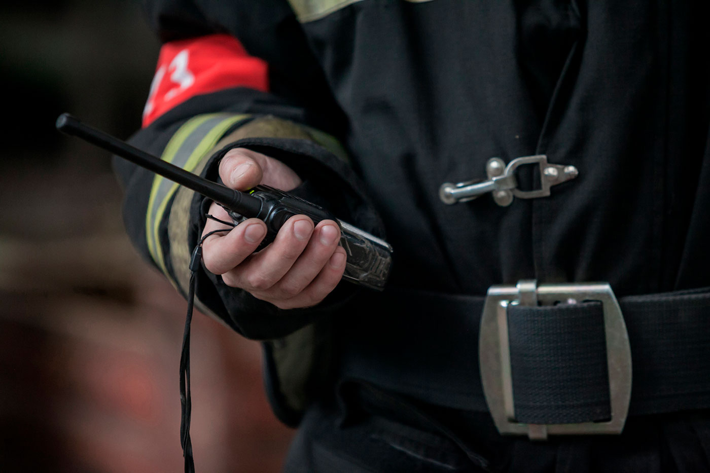
LMR, or Land Mobile System, is a terrestrially-based professional push to talk communications system, which is widely used by public safety organizations (for instance, police, firefighters and others) with the aim of supporting the communication in critical situations. This system is wireless, it works without any cables. LMR systems are used worldwide in various spheres from industrial to security and even military.